How Can PCB Milling Machines Cut Faster Without Ruining Fine Traces?
Why Do PCB Milling Machines Still Matter for Prototyping?
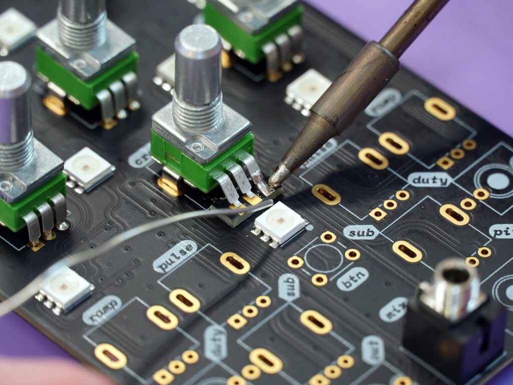
If you build electronics, pcb milling machines give you a direct way to cut copper, drill holes, and test a board before you place a factory order. You can check other industrial equipment categories in the Machines section, but PCB milling needs a separate look because the board is thin, the tools are small, and one burr can break a signal path. The goal is not to replace every PCB factory. The goal is to close the time between a design file and a board you can hold in your hand.
Fast Board Iteration without Wet Chemistry
A milling machine removes copper by cutting, so you do not need etching tanks, developer, or chemical cleanup after the job. For a two-layer sensor board or a quick test jig, that can change a half-day wait into a same-shift check. This helps when a connector footprint is off by 0.5 mm, or when a mounting hole hits a housing rib. The board may be simple, but it can save a full purchasing loop.
Local Control for Sensitive Designs
Some teams do not want early files leaving the lab. A local machine lets you keep a motor-control board, defense-related test board, or pre-release consumer device layout inside your own shop. It does not remove the need for file control, operator rules, or clean storage. It just gives you another option when the first prototype is too early, too rough, or too confidential to send outside.
Lower Risk Before Batch Fabrication
Scrap is easy to forget until bad boards start stacking up on the bench. The ITU and UNITAR Global E-waste Monitor 2024 reported that the world generated 62 billion kg of e-waste in 2022, while only 22.3 percent was formally collected and recycled. One small prototype board is not the whole issue, of course, but failed trial runs, rejected panels, and unused electronics all belong to the same bigger waste problem. A milled proof board can help you find layout errors before batch fabrication makes the mistake bigger. (itu.int)
What Specs Decide Real Milling Quality?
Buying from a spec sheet can be misleading. A low price looks nice, a high spindle speed sounds strong, and then the first 0.2 mm isolation path pulls up copper. Good PCB milling depends on many small things working together. The machine frame, spindle, table, software, cutter, and board holding method all leave a mark on the finished trace.
Spindle Runout and Trace Width
Runout is one of the first points to check. If the tool tip wobbles, the cut becomes wider than the toolpath, and fine traces can disappear. For a real buying check, ask for sample cuts on the same copper-clad laminate you plan to use. Look at the corners, narrow gaps, and ground pour edges, because those areas show the problem fast. A clean sample tells you more than a polished brochure. If your boards use 0.15 mm to 0.25 mm isolation, even a small runout change will show up clearly.
Motion Rigidity and Table Flatness
A PCB is thin, and the copper layer is much thinner than normal machining stock. If the table is not flat, one corner may cut too deep while another corner only scratches the copper. A stiff frame also matters because V-bits and micro end mills do not handle chatter well. Ask whether the machine supports surface probing or height mapping. It is not an exciting feature on paper, but it can save you from spending an afternoon chasing uneven cuts.
Software Flow from Gerber to Toolpath
The software path should be simple and predictable. You need clean import from Gerber, Excellon drill files, and board outlines. You also need tool libraries, step-down settings, safe travel height, and a preview before cutting. A common shop mistake is running a toolpath that looks right on screen but uses the wrong cutter angle or depth. When that happens, the first board becomes paid training.
Which Materials and Tools Should You Match?
PCB milling machines do not cut only one material. FR4 is common, but aluminum-backed boards, copper-clad ceramic, phenolic paper laminate, and soft fixture plastics can show up in the same workshop. The right setup depends on how the material cuts, what cutter shape you use, how chips leave the cut, and how clean the edge needs to be for your design.
FR4 Needs Dust Control and Sharp Bits
FR4 is strong because glass fiber sits inside epoxy resin. That same structure wears cutters quickly. Dull tools heat the laminate, smear resin, and leave torn copper edges. The OSHA Technical Manual on advanced composites notes that glass fibers can irritate skin, eyes, nose, and throat, and it also states that machining and finishing cured composite parts can generate very fine dust. For PCB milling, that means you should use an enclosure, local suction, careful cleaning, and no casual air blowing across the bench. (osha.gov)
Aluminum and Copper Need Different Feeds
Copper is sticky compared with glass-filled laminate, and aluminum-backed boards bring heat flow plus burr risk. If you use one feed rate for every board, the cut may pass in FR4 and look poor in aluminum-core LED boards. Use sharp tools, steady chip removal, and a safe depth of cut. It is also worth keeping a short log with material, cutter, spindle speed, feed, depth, and result. After ten boards, that notebook is often more useful than memory.
Vacuum Tables Improve Thin Board Holding
Thin boards can lift, bow, and vibrate during cutting. Tape can work for a one-off board, but it may add thickness error or leave adhesive on the back. Vacuum tables, pin location, and low-profile clamps give better repeatability from board to board. If a board shifts even a little during drilling, plated-hole alignment can become a problem later. For small factories, steady holding is often the quiet difference between hobby output and usable prototype production.
How Can You Judge Safety and Workshop Fit?
A PCB mill sits between electronics work and machining work. It creates dust, noise, chips, broken tools, and sharp board edges. Before you buy, check how the machine fits your room, operators, cleaning routine, and customer audit needs. A clean-looking machine will still make poor results if the workflow around it is messy.
Enclosure and Dust Capture First
An enclosure keeps dust and broken micro cutters inside the working area. Dust capture should be close to the cut, not placed far behind the machine. If you cut FR4 often, ask about filter grade, filter change access, and whether the vacuum path is sealed well enough for fine powder. A respirator is not a replacement for capture at the source. It is only a backup layer when your safety review says it is needed. See also: Materials.
Noise Heat and Daily Cleaning
Small spindles can sound sharper than expected, especially in a quiet electronics lab. Heat also needs attention. A spindle that runs near its limit for long isolation jobs may drift, and a hot cutter can darken resin at the cut edge. Daily cleaning should be easy to do: vacuum, wipe, inspect rails, check collets, and remove dust from the enclosure corners. Skip that for a week and the machine will start to feel worn before it should.
Compliance Records for Export Buyers
Export customers often ask direct questions: What material was used? Which process made the sample? Was dust controlled? Were operators trained? IPC lists IPC-A-600M as a global acceptability standard for printed boards and points to IPC-6012F for rigid board qualification and performance. IPC also lists IPC-4101E-WAM1 for base materials used in rigid and multilayer printed boards. These standards do not pick the machine for you, but they give buyers and suppliers the same language when they talk about board quality. (ipc.org)
How Should You Buy PCB Milling Machines for Production?
For production support, do not buy only because the demo board looks nice. Buy for the work you handle every week. That might be five small design revisions, fixture boards for assembly, low-volume sensor modules, or quick panels for a sales sample. A machine that matches the work will be used often. A machine that does not match the work will sit in the corner with one broken V-bit in the drawer.
Start with Sample Boards
Send your own file and material to the supplier when you can. Include the narrowest trace, smallest drill, tightest copper gap, and the actual board outline. Ask for photos before cleaning and after cleaning, because both views tell you something. If the board needs double-sided alignment, include that in the test as well. A supplier who refuses all real sample testing may still sell a good machine, but you will be taking more risk.
Check Support Spare Parts and Training
PCB milling uses consumables every week. Collets wear, cutters break, dust filters clog, and spoil boards need replacement. Ask how fast spare parts ship, which tools are standard, and how training is delivered. A machine with sound mechanics but weak support can cost more than a higher-priced model with stable parts supply. This is especially true for overseas buyers who cannot wait three weeks for a simple clamp or belt.
Calculate Cost per Usable Prototype
The purchase price is only one part of the cost. Count cutters, copper-clad boards, operator time, setup, dust filters, rework, and failed boards. Then divide that by usable prototypes. If a machine cuts three good boards in an hour but breaks tools every other job, the real cost goes up fast. If another model runs slower but gives clean boards with less babysitting, it may be the better production tool. No public authority publishes one universal ranking for all PCB milling machines, so sample evidence and shop math still matter most.
FAQ
Q1: Are PCB Milling Machines Good for Fine-Pitch Components? A: Yes, if spindle runout, table flatness, tool choice, and probing match your trace and gap targets. Test with your smallest footprint before buying.
Q2: Can You Mill FR4 Safely in a Small Workshop? A: You can, but you need an enclosure, dust capture, careful cleaning, and a proper safety review. FR4 dust should not be treated like normal sawdust.
Q3: Do PCB Milling Machines Replace Factory PCB Fabrication? A: Not for multilayer boards, plated vias, solder mask, or large repeat orders. They work best for quick prototypes, fixtures, layout checks, and low-volume engineering boards.
Q4: What Is the Most Important Spec to Check First? A: Check real sample quality first, then spindle runout, machine rigidity, table flatness, software flow, and support. A real board sample is more useful than a long spec list.
Q5: How Do You Reduce Tool Breakage? A: Use sharp cutters, correct collets, light depth of cut, steady board holding, clean dust removal, and sensible feed rates. Keep spare tools close too; tiny cutters do not forgive mistakes.