Gantry mill selection guide for large-part machining

What a gantry mill is and why the design matters
A gantry mill is a CNC milling machine with a bridge or portal spanning the work area. The spindle or machining head travels over a large table, bed, or floor-mounted work zone. Shops typically consider this architecture when a part is too long, wide, heavy, or difficult to fixture for a conventional vertical machining center, but still needs milling, drilling, boring, tapping, surfacing, or contouring in a controlled setup.
The appeal is reach with support. The cutting head moves above the workpiece while the part remains supported across a broad table or bed. The trade-off is that the buying decision cannot stop at spindle power and axis travel. Foundation requirements, thermal behavior, calibration, chip and coolant handling, operator access, and loading method all affect whether the machine will perform as expected.
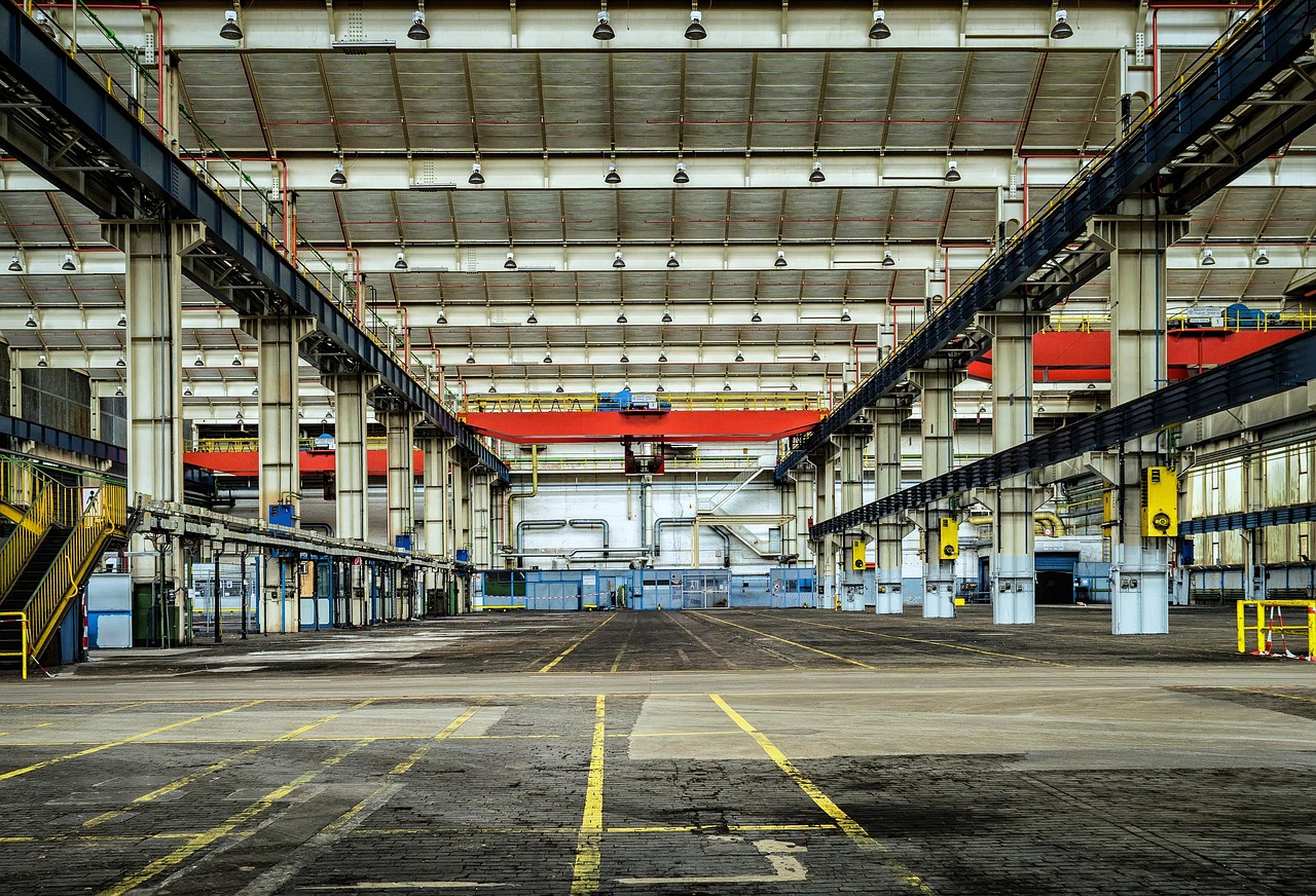
Machine-tool builders use overlapping terms such as bridge mill, portal mill, double-column machining center, bridge-type machining center, and gantry machining center. The wording varies by builder and region. For that reason, it is safer to compare the actual architecture, working envelope, head configuration, table design, and acceptance data rather than relying on the name alone.
For terminology, ISO 10791 describes machining centers as numerically controlled machine tools capable of multiple operations such as milling, boring, and tapping, usually with automatic tool changing from a magazine or similar storage system. Many gantry mills fall within this broader machining-center category when they include CNC control, automatic tool handling, and multi-operation capability.
How the gantry architecture supports large-part machining
The defining feature is the load path. Instead of relying on a small column or knee-type structure to carry a large overhung head, a gantry mill uses two side structures and a crossbeam or bridge to span the work area. The head moves along the bridge, while the bridge, table, or both may move depending on the machine design. This arrangement gives the machine a large rectangular working envelope while keeping the spindle supported close to the cutting zone.
Fixed table, moving table, and moving gantry designs
In a fixed-table design, the workpiece stays in place while the bridge or spindle assembly moves. This can be useful for very heavy parts because the machine does not need to accelerate the part itself. In a moving-table bridge machine, the table carries the part through one axis while the bridge and head provide the other movements. That layout can simplify the structure at some sizes, but table load, table deflection, and acceleration limits become critical. In very large installations, a moving gantry or portal may travel over a bed or floor plate, reducing the need to move massive workpieces.
Common axis and head configurations
A basic gantry mill may provide three linear axes for prismatic work. More advanced machines may use indexing heads, universal heads, right-angle heads, fork-type five-axis heads, rotary tables, or mill-turn tables. A 3+2 setup can position the head or part at an angle and then cut with the axes locked. Full five-axis interpolation can be valuable for contoured aerospace, die, mold, energy, marine, and heavy-equipment parts, but it also raises the requirements for programming, collision checking, calibration, and operator training.
When a gantry mill makes sense compared with other machines
A gantry mill is not the best choice for every large component. It fits best when the part benefits from broad support, top-down access, long X or Y travel, and the ability to machine several faces or features without repeated refixturing. The comparison below shows where it sits among related machine types.
| Machine type | Typical strength | Typical limitation | Good fit |
|---|---|---|---|
| Gantry mill or portal mill | Large work envelope with bridge-supported spindle access | Requires careful foundation, guarding, loading, and calibration planning | Large plates, frames, molds, dies, weldments, castings, and structural parts |
| Bridge-type vertical machining center | Rigid double-column structure for medium to large workpieces | May have less flexibility than an open floor-type setup for extremely long parts | Large molds, machine bases, precision plates, and multi-surface work |
| Floor-type boring or milling machine | Excellent side access and flexibility for tall or long components | May require more setups for top-face milling or wide-area surfacing | Heavy fabrications, housings, turbines, and parts needing side boring |
| Large horizontal machining center | Strong chip evacuation and multi-face work with pallets or rotary tables | Part size and weight may be limited by pallet and rotary table capacity | Box-shaped parts, housings, repeat production, and fixture-based workflows |
The practical decision often comes down to the part family. If most work involves broad top surfaces, long slots, mold cavities, large bolt patterns, or complex contours on a supported component, a gantry mill can reduce repositioning. If the work is dominated by deep horizontal bores, side-facing features, or extremely tall structures, a floor-type machine may deserve equal consideration.
Specifications that deserve more attention than maximum travel
Catalog travel is only a starting point. A machine with large X, Y, and Z numbers can still be a poor fit if usable clearance, spindle reach, fixture height, head length, tool length, chip flow, or crane access does not match the real parts. A useful selection process starts with the largest, heaviest, most awkward, and most tolerance-critical parts expected over the next several years.
Work envelope and clearance
Check the distance between columns, table size, maximum workpiece height, spindle nose to table distance, tool length allowance, and head rotation clearance. A five-axis head may reduce the usable envelope at certain angles, and right-angle heads also consume space. If fixtures, tombstones, riser blocks, probes, or vacuum plates will be used, include them in the envelope model before selecting the machine.
Spindle power, torque, and speed range
Large-part machining may require both heavy roughing and fine finishing. Steel, cast iron, aluminum, composites, and hardened materials place different demands on torque, speed, tool interface, cooling, and vibration control. High spindle speed alone does not guarantee productivity if torque is insufficient for large cutters. High torque alone does not guarantee finish quality if the machine lacks thermal stability, smooth axis control, or suitable tooling.
Table load and part support
Table load should be evaluated together with load distribution. A concentrated weldment, a long casting with uneven feet, or a thin plate clamped at the edges can behave very differently from a uniformly distributed block. Foundation condition, table flatness, support pads, clamps, and fixture strategy all influence accuracy and repeatability. On large thin parts, the workpiece itself may deflect more than the machine, so process planning needs to include support points and machining sequence.
Accuracy, calibration, and acceptance testing
For a gantry mill, accuracy is not a single number. Geometric alignment, positioning accuracy, repeatability, straightness, squareness, spindle performance, rotary-axis behavior, thermal drift, volumetric error, and cutting performance all matter. ISO 10791 and related ISO 230 test methods are commonly referenced for machining-center evaluation, while machine-tool calibration research distinguishes errors within an axis, errors between axes, and volumetric errors across the working space. See also: Materials.
The larger the machine, the more important it is to define where accuracy is required. A tolerance that applies only in a small working zone may need a different acceptance approach than a tolerance that must hold across the full table length. Buyers and machining planners should ask whether acceptance will include laser measurement, ballbar testing, spindle tests, probing routines, test cuts, volumetric compensation, thermal warm-up procedures, or a customer-specific part trial.
| Selection question | Why it matters | Evidence to request |
|---|---|---|
| What is the usable envelope with the intended head and tools? | Published travels may not equal collision-free machining space | Layout drawing, simulation, or reach study |
| How is accuracy verified across the required working zone? | Large machines can vary by position, temperature, and load | Acceptance test plan and calibration report |
| What are the spindle options for the target materials? | Roughing, finishing, and high-speed work need different torque and speed profiles | Power and torque curves, tool-interface details |
| How will chips, coolant, and mist be controlled? | Large open work areas can spread chips and fluid if guarding is weak | Guarding layout, coolant plan, mist-control plan |
| What foundation and environmental controls are required? | Accuracy depends on installation, leveling, temperature, and vibration | Foundation specification and site-preparation checklist |
Safety, coolant, and maintenance limits
Large open machines create risks that smaller enclosed machining centers may control more easily. OSHA machine-guarding guidance identifies the point of operation, power transmission devices, and operating controls as fundamental areas to address. For a gantry mill, guarding, access control, emergency stops, safe loading procedures, chip containment, operator visibility, and lockout practices should be designed into the installation rather than added later.
Coolant and metalworking-fluid management also need early attention. OSHA guidance on metalworking fluids emphasizes fluid selection, hazard communication, concentration control, pH, biological contamination, tramp oil, and housekeeping. On a gantry mill, long runs, large sumps, chip conveyors, washdown systems, mist collection, and open work areas can make fluid management more complex. Poor control may affect tool life, part quality, worker exposure, machine cleanliness, and unplanned downtime.
Maintenance planning should cover way covers, linear scales, encoders, lubrication systems, spindle cooling, head attachments, tool changers, probes, cable carriers, and chip-handling equipment. Because gantry mills are often tied to high-value parts and long cycle times, preventive maintenance intervals should be realistic for the shop’s production schedule, not copied blindly from a generic checklist.
Practical questions before buying or outsourcing
Whether a company is purchasing a machine or choosing a supplier with gantry milling capacity, the same core questions apply. The goal is to match the machine, process, and risk profile to the part family. For more machine-tool explainers and industry topics, browse the Machines section.
- What is the largest part envelope after fixtures, clamps, and inspection access are included?
- Which faces and features must be finished in one setup?
- Which tolerances are local, and which must hold across the full part length?
- Will the work require three-axis, 3+2, or full five-axis machining?
- What materials will dominate the workload, and what cutters are expected?
- Can the shop crane, loading route, and floor support the heaviest part safely?
- How will thermal drift be managed during long cycles?
- What inspection method will confirm the finished part?
- How will chips, coolant, and mist be contained and removed?
- What backup plan exists if a spindle, head, scale, probe, or control component fails during a long project?
A gantry mill can be a strong productivity tool, but only when the surrounding process is mature enough to use it. Programming, fixturing, lifting, probing, tool management, maintenance, and inspection are part of the real capacity. A machine that looks oversized on paper may still be economical if it eliminates multiple setups and reduces part movement. A machine that looks powerful on paper may underperform if it lacks the head configuration, calibration strategy, or shop support needed for the actual work.
Frequently asked questions
Is a gantry mill the same as a bridge mill?
The terms often overlap, but they are not used consistently. In many catalogs, a bridge mill or portal mill refers to a machine with two columns and a crossbeam supporting the spindle head. A gantry mill may also describe a moving-gantry machine that travels over a fixed work area. Always compare the machine layout and specifications rather than relying only on the name.
What parts are commonly machined on a gantry mill?
Common candidates include large molds, dies, machine frames, fabricated weldments, base plates, aerospace structures, rail and energy components, marine parts, and heavy-equipment castings. The common thread is not size alone; it is the need to machine a large or awkward component with enough support, reach, and accuracy.
Does a gantry mill need five-axis capability?
Not always. Three-axis machines can be highly effective for surfacing, drilling, boring, pocketing, and planar features. Five-axis or 3+2 capability becomes more valuable when the part has angled faces, deep cavities, complex contours, or multiple orientations that would otherwise require repeated setups.
What is the most overlooked specification?
Usable machining space is often overlooked. Buyers may focus on maximum axis travel, but the real limit may come from column clearance, head length, fixture height, tool length, rotary movement, chip evacuation, crane access, or probing clearance. A practical reach study is often more useful than a travel number alone.
How should accuracy be discussed with a supplier?
Ask for the specific measurement method, working zone, temperature condition, load condition, and acceptance criteria. For critical work, general claims about precision are not enough. The discussion should connect machine calibration, test cuts, probing, inspection, and the actual tolerance map of the part.