CNC wood design for manufacturable parts, joinery, and clean edges

What CNC wood design means in practical manufacturing
CNC wood design is the process of creating wood parts, panels, decorative surfaces, fixtures, and joinery that can be cut accurately on a computer numerical control router or mill. For sourcing and manufacturing teams, the key issue is straightforward: a good-looking drawing is not automatically a production-ready file. The design has to match the material, cutter diameter, machine travel, hold-down method, feed and speed limits, toolpath strategy, and finishing plan. Public guidance from the USDA Forest Products Laboratory, OSHA, Autodesk, ShopBot, Amana Tool, and CNC router manufacturers points to the same practical lesson: the earlier design decisions account for wood behavior and machining limits, the fewer surprises appear during cutting, assembly, sanding, and delivery.
For buyers comparing suppliers, sourcing a CNC wood project should involve more than a price for cutting time. It should include a review of drawings, material thickness, grain direction, tolerance expectations, visible faces, dust and safety controls, and whether the supplier can turn design intent into stable CAM toolpaths.
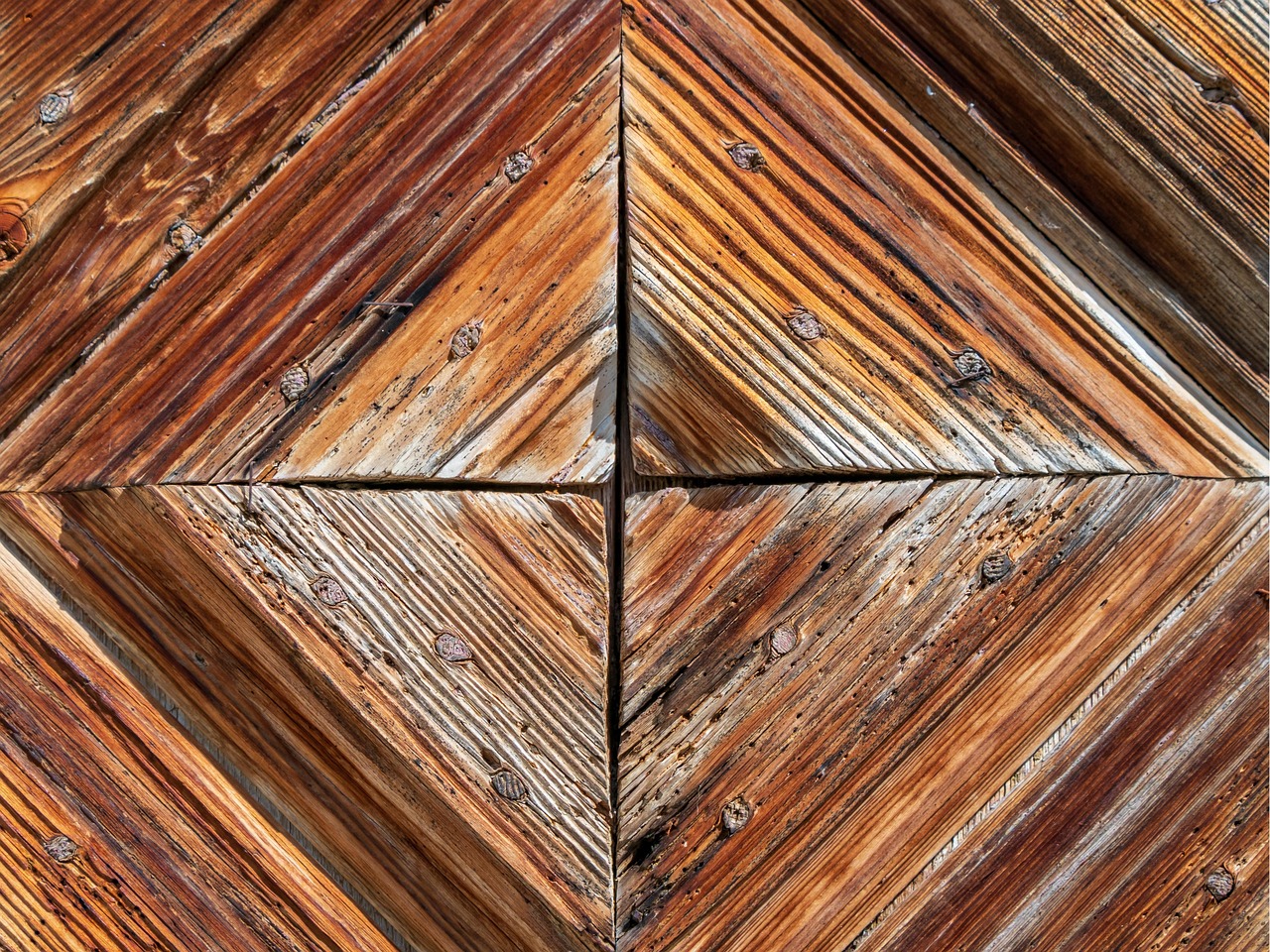
Start with the search intent behind the design
The phrase “cnc wood design” can mean several things. Some users are looking for decorative relief files, some need furniture or cabinet parts, and others want production-ready design rules for routed wood components. In a manufacturing context, the most useful interpretation is design for CNC routing: turning a concept into wood parts that cut cleanly, fit consistently, and can be repeated without excessive manual correction.
That intent changes the design process. A sign maker may focus on lettering depth, V-carve contrast, and finishing. A furniture producer may care more about slots, tabs, fasteners, board movement, and nesting efficiency. A packaging or fixture buyer may prioritize repeatability and cost per sheet. The same CNC router can serve all of these jobs, but the design file cannot be handled in the same way.
A practical CNC wood design brief should define:
- The final part function, not just the visible shape.
- The wood species or sheet material, including nominal and actual thickness.
- Which faces and edges will remain visible after assembly.
- Required tolerances for joinery, fastener holes, grooves, and pockets.
- Expected finish, coating, sanding level, or post-machining process.
- Batch quantity, because one prototype and 500 nested panels require different decisions.
This is where many avoidable problems begin. If the buyer sends only a decorative vector file, the supplier may have to make assumptions about cutter size, tab placement, stock thickness, and finish allowance. Those assumptions can affect cost and quality more than the artwork itself.
Material behavior should shape the CAD file
Wood is not an inert plastic sheet. It is anisotropic, porous, and moisture-sensitive. The USDA Forest Products Laboratory’s Wood Handbook explains that wood properties vary with direction and moisture content. In everyday production terms, movement across the grain is usually more important than movement along the grain, and solid wood behaves differently from plywood, MDF, and laminated panels.
For solid wood parts, grain direction should be considered before toolpaths are created. Long narrow parts cut across unstable grain may cup, bow, or split more easily than parts oriented with better support. Thin carved areas may become fragile when the grain runs through them in the wrong direction. Deep pockets can expose internal stress, especially when material has not acclimated to the shop environment.
Sheet goods reduce some of these risks but introduce others. Plywood thickness can vary from its nominal size, veneer faces can chip, and internal voids may affect small details. MDF machines consistently but produces fine dust and can be weak at thin screw edges. Laminated panels may require tool choices that protect both the top and bottom surfaces.
A manufacturable CAD file should state the material assumption clearly. “18 mm plywood” is not always enough. The drawing should show whether the slot is designed around actual measured thickness, whether visible faces need special protection, and whether a finishing pass is included to remove tool marks. With tab-and-slot joints, even a small material thickness mismatch can turn a press fit into a loose joint or an assembly problem.
Design around the round cutter, not an ideal corner
One of the most common CNC wood design mistakes is drawing sharp inside corners as if a router bit could cut a perfect square pocket. A rotating round cutter always leaves an inside radius related to the tool diameter. ShopBot’s educational materials and many CNC training examples describe the practical solution: add dogbone, T-bone, or relief fillets where square tabs need to fit into internal corners.
This is not just a cosmetic detail. It determines whether a shelf tab, stool leg, cabinet partition, or press-fit box can actually assemble. If a square mating part enters a rounded internal corner, the uncut radius blocks full seating. Designers sometimes discover this only after cutting the first sheet, when every slot needs hand chiseling. A small dogbone added in CAD is usually cheaper than manual rework.
Common design rules for routed joinery
- Match slot width to the measured material thickness, not only to the catalog thickness.
- Add dogbone or relief features only where they are functionally needed.
- Keep relief features consistent so the finished part looks intentional.
- Leave enough material around holes, tabs, and edges to avoid breakage.
- Use test coupons before committing a full sheet to press-fit joinery.
Dogbones are especially important for flat-pack furniture, jigs, display structures, and architectural panels with interlocking ribs. For visible decorative work, designers may prefer hidden reliefs, rounded mating parts, or an assembly detail that accepts the router radius rather than fighting it.
Tool selection affects edges, tearout, and machining cost
Tooling choices should be made before the design is considered complete. A 3 mm bit can create finer internal details than a 6 mm bit, but it may require slower cutting, shallower passes, and more careful tool management. A larger bit is stiffer and faster but cannot reproduce small radii. If the drawing contains many narrow grooves or small internal corners, the design may require a tool change or a slower finishing pass.
Router bit geometry matters as much as diameter. Manufacturer guidance commonly distinguishes upcut, downcut, straight, and compression tools. An upcut bit pulls chips upward and helps evacuation, but it can lift fibers on the top face. A downcut bit can protect the top surface but pushes chips downward, which may be unsuitable for deep pockets without chip clearance. A compression bit combines upward and downward cutting action and is often used for plywood or laminated panels where both faces need cleaner edges.
| Design need | Likely tooling consideration | Design implication |
|---|---|---|
| Clean top face | Downcut or scoring strategy | Allow chip evacuation and avoid overly deep single passes |
| Clean top and bottom faces | Compression bit | Material thickness and first-pass depth must suit the compression geometry |
| Fine internal details | Smaller diameter bit | Expect slower cutting and greater risk of tool deflection |
| Fast profile cutting | Larger, stiffer bit | Internal corner radius increases |
| High-quality visible edge | Roughing plus finishing pass | Leave a small allowance for the final pass |
Feed and speed settings are also part of design reality. Amana Tool’s published machining formulas express feed rate as RPM multiplied by flute count and chip load. The exact values depend on the tool, material, machine rigidity, hold-down, and depth of cut, so a public chart should be treated as a starting point rather than a universal setting. The design takeaway is that very delicate geometry can increase machining time even when the part looks small.
Toolpaths, tabs, nesting, and hold-down are design decisions
CAD defines the shape, but CAM defines how that shape is cut. Modern CAD/CAM platforms, including widely used systems such as Autodesk Fusion, connect models to toolpaths, setups, tool libraries, and machining operations. For CNC wood projects, the toolpath plan often determines whether a design is economical. See also: Machines.
Several choices deserve attention early:
- Cut order: Internal pockets and holes are usually machined before outer profiles so the part remains stable.
- Tabs: Small bridges keep parts from shifting after profile cuts, but they add trimming and sanding work.
- Onion-skin cutting: Leaving a thin layer at the bottom can help hold small parts until a final pass releases them.
- Lead-ins and ramps: Gradual entry can reduce tool marks and stress compared with plunging straight down.
- Nesting: Sheet layout affects material yield, grain direction, vacuum hold-down, and part identification.
Hold-down is particularly important in wood routing because cutting forces, chip evacuation, and vibration can move the part. Vacuum tables are common in production, while clamps, screws, wedges, or tape-and-adhesive methods may appear in prototype work. If clamps or screws are used, the design must leave safe zones for them. It should also avoid tiny loose pieces that can become projectiles or be pulled into dust collection.
A file that ignores hold-down may look efficient on screen but fail during cutting. Small parts need tabs, onion skin, fixture planning, or a revised layout. Large panels may need sequencing that keeps vacuum pressure effective until the final operation. These are not afterthoughts; they are part of manufacturable CNC wood design.
Safety, dust, and finishing should not be separated from design
Wood dust is both a health and housekeeping issue. OSHA’s wood dust materials discuss respiratory and other health effects, and OSHA’s woodworking guidance also points to dust control near the source. NIOSH has recommended an exposure limit of 1 mg/m³ total dust for wood dust. For CNC routing, this matters because routers can generate fine dust continuously while the toolhead moves across a large area.
Design decisions can influence dust and cleanup. Deep narrow pockets trap chips and heat. Fine 3D relief carving produces large amounts of small particles. MDF creates fine dust that requires stronger collection discipline than many solid wood operations. A design with excessive fine detail may therefore increase machining time, dust collection load, tool wear, and finishing labor.
Combustible dust considerations may also apply in industrial woodworking environments. The exact obligations depend on the facility, jurisdiction, equipment, and dust volume, so the responsible path is to review applicable OSHA, NFPA, and local requirements rather than relying on a generic checklist. For sourcing purposes, buyers should ask whether the supplier has suitable dust collection, machine guarding, emergency stops, housekeeping procedures, and material-specific controls.
Finishing should also be planned before cutting. If the part will be painted, slight edge fuzz may be acceptable after sanding. If it will receive a clear finish, tearout, burn marks, and inconsistent grain direction become more visible. If the design includes engraved lettering, the finishing sequence may affect contrast and legibility. A good design leaves enough allowance for sanding and does not place fragile raised details where they will be damaged during post-processing.
A sourcing checklist for CNC wood design files
Before sending a CNC wood design for quotation or production, review it as a manufacturing package rather than a single drawing. The following checklist helps reduce ambiguity between the designer, buyer, and CNC supplier.
- Confirm the material: Specify solid wood, plywood, MDF, laminated panel, or another wood-based board. Include actual thickness where joinery matters.
- Mark visible faces: State which side must remain clean so the supplier can choose tool direction and hold-down strategy.
- Define tolerances: Separate decorative tolerance from functional fit tolerance. A wall panel and a press-fit joint do not need the same control.
- Check inside corners: Add dogbones, radii, or relief features where square mating parts must fit.
- Review minimum feature size: Make sure grooves, islands, lettering, and small holes can be cut with available tool diameters.
- Plan tabs and release strategy: Decide how parts stay attached during cutting and how tab marks will be removed.
- Allow finishing stock: Include sanding, coating, or final trimming needs in the drawing or production note.
- Request a test cut: For new materials, tight fits, or visible joinery, a small coupon can validate the design before full production.
This checklist is especially useful when designs move across borders, software systems, or supplier networks. A DXF, SVG, STEP, or native CAD file may carry geometry, but it may not carry manufacturing intent. Clear notes reduce the risk that the supplier chooses a toolpath that technically follows the line but misses the functional requirement.
Frequently asked questions
What file type is best for CNC wood design?
There is no single best file type for every job. 2D profile cutting often uses vector formats such as DXF or SVG, while 3D carving and complex assemblies may use STEP, STL, or native CAD files. The better question is whether the file preserves scale, layers, part names, material notes, and machining intent.
Why do CNC wood parts have rounded inside corners?
A CNC router uses a rotating round bit, so it cannot create a perfectly sharp internal corner. The remaining radius depends on the tool diameter. If a square tab must fit into that corner, the design usually needs a dogbone, T-bone, mating radius, or another relief strategy.
Can the same design be cut from plywood and solid wood?
Sometimes, but it should not be assumed. Plywood is dimensionally stable in many sheet applications, while solid wood movement depends strongly on grain direction and moisture. Joinery clearances, finishing, screw placement, and part orientation may need revision.
What causes tearout in CNC wood cutting?
Tearout can come from dull tooling, unsuitable bit geometry, poor support, aggressive depth of cut, weak hold-down, wrong cut direction, or material defects. Design can reduce the risk by marking visible faces, allowing finishing passes, avoiding unsupported fragile features, and selecting tooling with the supplier.
Is CNC wood design only for decorative carving?
No. Decorative carving is one use, but CNC wood design also supports cabinet parts, fixtures, furniture components, acoustic panels, signage, molds, templates, jigs, and architectural elements. The common requirement is a design that respects material behavior and machining constraints.


